Quote from: retired2 on June 03, 2015, 06:09:44 AMQuote from: DennisCA on June 02, 2015, 09:45:51 PM
No pics but I can see that the epoxy had let go, the bond wasn't very strong after all. So only the screws held it in place and they had been pulled straight through the the plywood bottom when things let go, one vane shot off into the ceiling and broke a fluorescent tube. These vanes are heavy and dangerous, I was lucky I put the circuit breaker on an extension cord and moved to the other side of the shop and stood crouched behind the jointer.
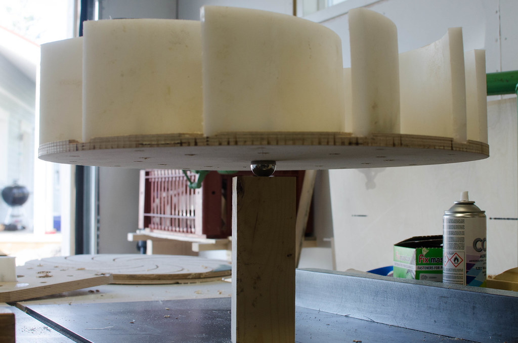
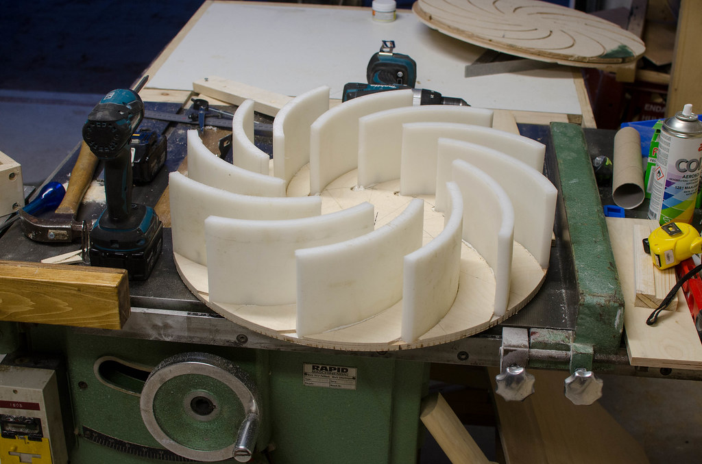
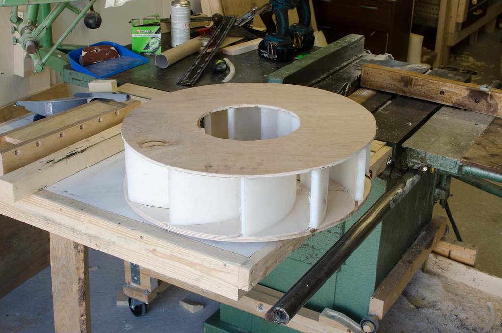
I'm remaking this but using plywood or MDF vanes like Marius hornberger used in his build- I think the lighter weight means there's less momentum to overcome as it starts up so less stress in that initial jolt, at least the vanes shold be light I now feel, the backing disc could probably be made heavier from 18mm plywood for deeper grooves.
Also I think the wood glue bond with wooden components will be a lot stronger than this failed epoxy joint, and safer if it blows up. Next time I'll be testing it with the top on too. I think I will follow Matthias wandels design closer in terms of vane layout for this new design, perhaps make it a little shorter, I had aimed for 10cm but perhaps 8cm will make for a stronger impeller.
Even with a successful build, I would always be worrying about when it was going to explode at full speed. Home built blowers, especially large ones, should be isolated from the rest of the shop with a "blast barrier" - a very strong one to keep it from adding to the amount of shrapnel in an explosion.
My solution to this is to put it in a separate storeroom that nobody is in. This will also save space in the shop.