News:

SMF - Just Installed!

Main Menu
Menu

Show posts

This section allows you to view all posts made by this member. Note that you can only see posts made in areas you currently have access to.

Show posts Menu

Messages - Lance

#1
Quote from: dwall174 on April 21, 2023, 02:20:31 PM
I guess I'm going to have to figure this one out myself!

I would guess that no one here has tried that exact set-up, so nobody wanted to give you an answer.  Some of the questions I have had, have been the same way. I was asking about somethings that no one has tried.  So, I am working on trying it myself...

The best thing I can say is give it a try and post up your results.  It may help the next person that is hoping for answers.

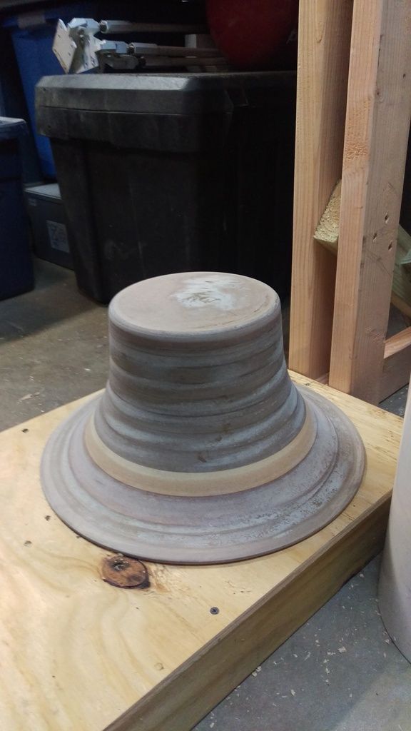
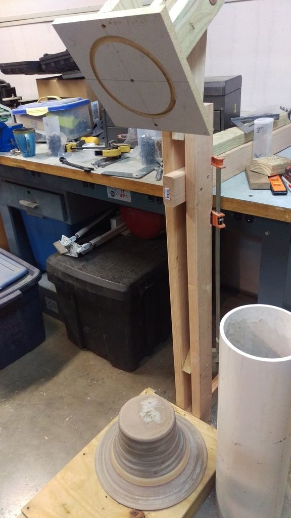
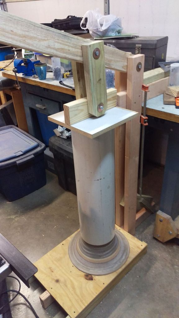
Lance
#2
I would be hesitant to make something from wood to use with most metalworking, but you could possibly make an all-metal separator.  If you have the metalworking skills I don't see why this wouldn't work.  If you just put a bucket with water at the bottom but have a wooden separator you might get hot metal pieces stuck in a wooden corner in the baffle somewhere that smolders for awhile then catches fire.
#3
I have been thinking about what to do if the 22.5" diameter does not work out with the 8" outlet... 

The cone portion of the cyclone design is there to aid in the separation of the chips and the height of that cone is crucial. if it is too short the separator does not stop the swirling air from disturbing the bin and lifting dust back into the separator.  That is where Phil's baffle comes in.  It eliminates the need for the cone.  It looks like everyone sizes their tophats to the bin it goes on top of.  That is what I am looking at doing, even with my 8" port sizes.  What popped into my mind is, just because I am using a baffle it doesn't mean I couldn't still use a cone also, Not the 30' tall cone a cyclone uses but a shorter cone just to go from a 30" tophat to a 22.5 in bin.  Maybe 8 to 10" tall?
Sorry for the crude drawing...

#4
I am using the 22.5" diameter for the tophat as that fits my 50 gal plastic drum. In the long run using a top hat may not work and I may have to go back to a cyclone.  I am hopeful that the tophat works as it is much shorter than the cyclone for this size of system.  The original cyclone I built had a body that was 18" in diameter with an 8" outlet port so I hope the 22.5 tophat will still work with the 8" port.  The original Blower, Cyclone and bin stood just under the available 9 foot ceiling in my old shop and I only had about 2 feet of height for the bin at the bottom. I was never happy with that.  Using a tophat design will allow the full-size bin to fit while keeping with an acceptable over all height. 

I know for some "Pentz" can be a dirty word around here, but I do believe there is some validity to his claims about the need to remove the fine dust particles from our shop air (or keep them out of the air to begin with).  I you haven't been there before it is worth going to billpentz.com and check out the basics tab.

I'm not Just attempting to clean up the bigger dust and chips, I'm trying to remove as much fine dust from the air around the tool as possible.  This means I am shooting for something closer to 1000 CFM at the tools.  Most of my tools will have custom larger ports added, but also in most cases multiple ports for each tool (for instance one above and one below the blade).  My blower was specifically made to move the volume of air you are talking about. It uses a 5hp motor with a 16" impeller.  I took readings for air speed at the inlet of the blower years ago when I made it, but I don't remember the numbers now.  I will have to re-test that when I start putting all of this together.  needless to say, it was well over the 1000 CFM at the blower, the trick is to keep the losses to a minimum as I add filter, seperator, ducting ports, etc.
#5
Hello all, 

My plans to build a tophat seperator got stalled a few years ago.  Finally, I'm starting this project back up.  I have a homemade impeller blower based on a Pentz design with 8" inlet and outlet.  I have most likely overlooked it, but I could not find any other posts or examples of others making any tophats this big.  Anyway, at this stage in my planning I wanted to make sure my dimensions for the top hat are big enough to handle the volume of air moving thru that 8" pipe. I am going to use Retired2's build as a reference to compare sizes. Here are my numbers, Please let me know if my logic looks sound:

(for those pedantic math nerds I will be rounding number on occasion.)

Retired2's tophat:
5" ports with 22.5 diameter which is 6" tall
  5"diamiter= (2.5*2.5)*pi=20sq"
  22.5" diameter = (11.25*11.25)*pi=397.6sq"
  397.6*6=2386ci
  The ratio between the area of the port and the volume of the tophat is 119:1  (397.6/20=119.3).  (I know I am comparing area to volume, but I think it works for what I am trying to accomplish)

My tophat:
8" ports with 22.5" diameter with a height of ???
   8" diameter= (4*4)*pi=50sq"
   using the Ratio above 397.6*50 gives me a target volume of 5950ci
   I then take the Volume and divide it by the area of the tophat:  5950/397.6=15"
   Now I have my height at 15"
   the rectangular port size should be 50"/15"=3.3"

There for I think I am going to make my tophat 22.5" in diameter by 15" tall with a port transitioning from a round 8" pipe to a square that is 15" tall x 3.5" wide.  Does that sound good or do some of you see anywhere I really went astray? 

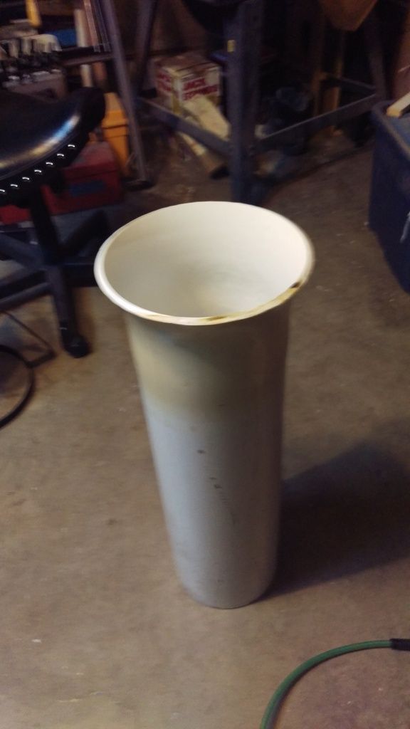
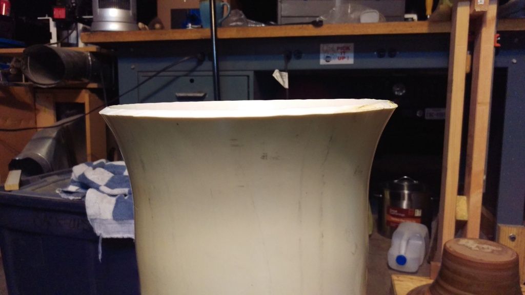
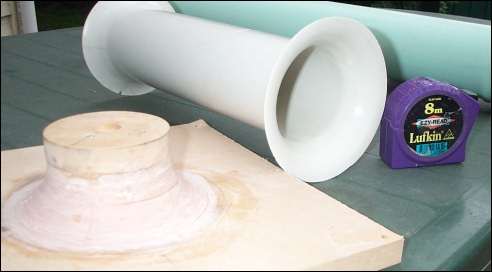
I know everyone here like the eye candy so here are some pics of the outlet pipe I created a few years ago when I started this whole thing.  It is an 8" thick-walled PVC pipe with a small bell mouth stretched into it.


The thick wall only let me stretch it a small amount, but I think it is enough to help.  Some of the whitepapers only showed the bell mouth curving about that far.

Thanks, Lance
#6
I agree about his finding with the Type E1 (3-vaned Bellmouth and central body) being his best found method of stopping swirl velocity but I would also question the loss of air volume by decreasing the overall size of the pipe by removing the center portion.  Is the extra bit of swirl cancelation with the loss of volume in the exit pipe of the separator.
#7
QuoteLance, It looks like the end of the pipe that first hits your form is cut square across with a pretty sharp edge.  Could it be trying to dig into the form?  I wonder if easing that edge might allow it to follow the form more easily.

I thought about that also.... after the fact.  I went back later and rounded those edges to help with airflow.  that's when I thought "I should have done this before hand".  The flip side was that using the veg oil to heat it worked well as lube.
#8
I have been thinking about it and right now my plan is going to be to add a three veined piece of aluminum.   
#9
Thanks!.  That's some deep stuff.  I see where the idea of the bell mouth came from but it makes me question the use of a bunch of plastic tubes as a de-swirl device.  If I read that correctly he had better results with the three bladed type then he had with the four bladed.  I think that stand to reason that moving from 3 or 4 sections up to around 20 separate sections may be massive overkill.  What do you guys think?
#10
Here is what happened. 
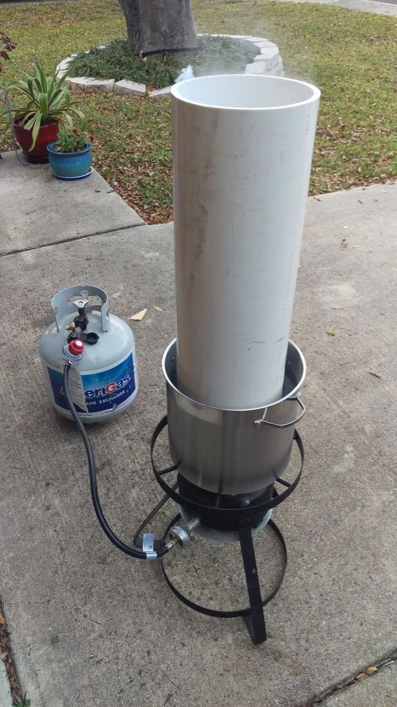
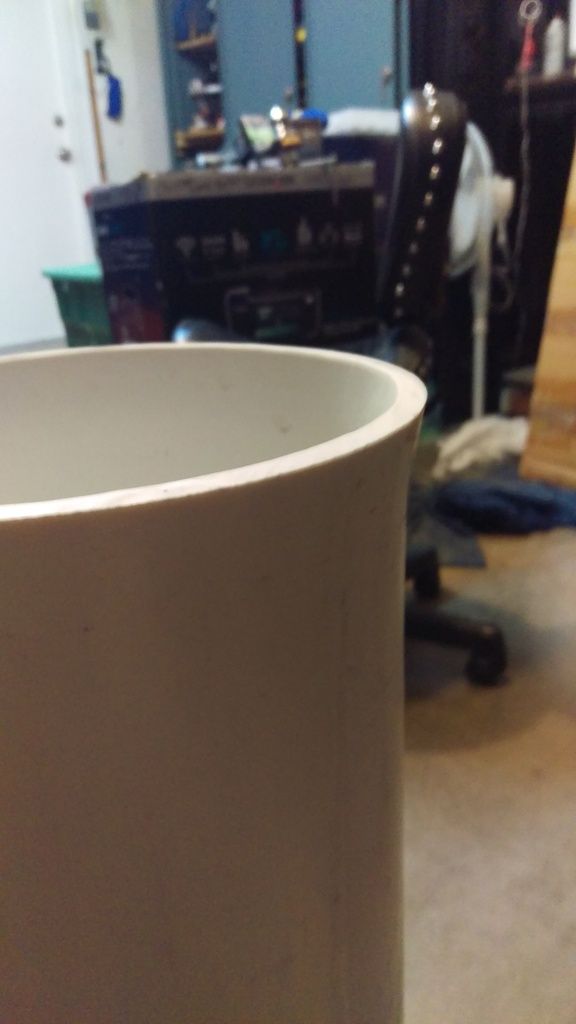
I brought a pot of water to a boil and then I placed the PVC in the pot for about 10 min checking every so often for flexibility of the PVC.  (FYI... the heat only transfers a small way up the PVC so the only part that becomes flexible is the portion directly in the water.  After it was flexible I placed it on my press but I could not get it to flair much at all.  I placed it back into the water to heat it back up.  after leaving it in for longer periods of time and multiple attempts I decided the water was just not hot enough.  the second pic is the best flare I could accomplish:


I then decided to try using vegie oil as it should attain a higher temp.  I seemed to be working until I realized the PVC was melting an burning on the bottom of the pot.......oops.  Now I am going to owe my wife a new pot.  thankfully it was a cheepy. :P 

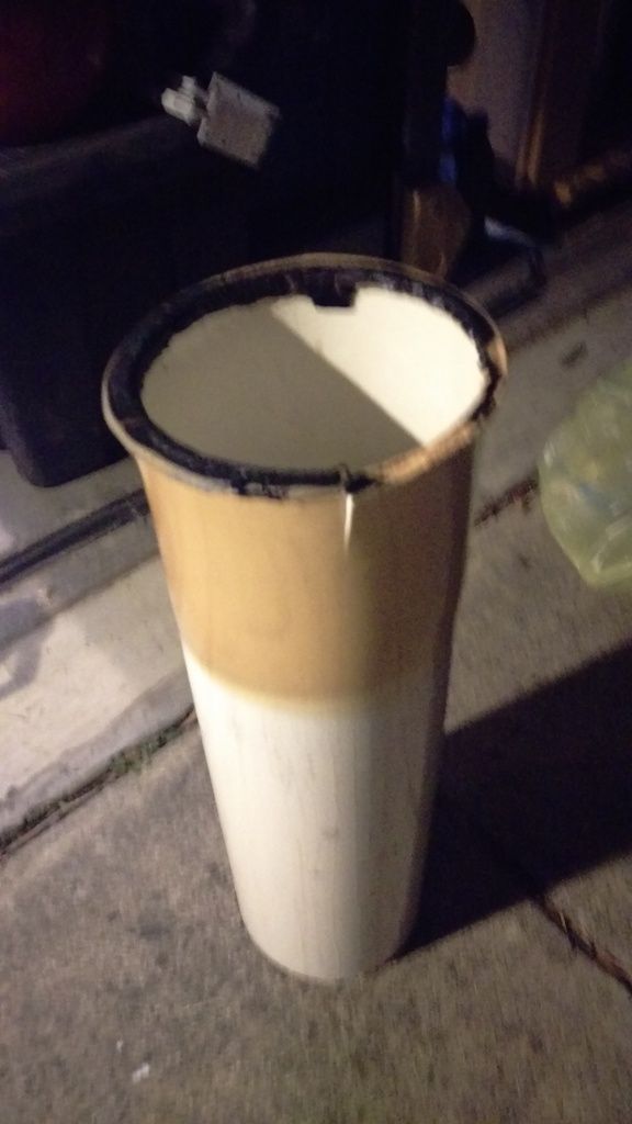
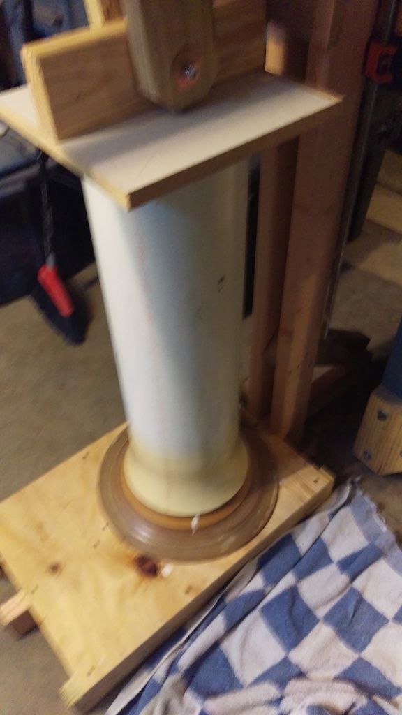
I then grabbed another pipe I had waiting.  This time we held it in the oil and kept it from touching the bottom.  This worked.  I put it on the mold and sure enough it was flaring nicely until it started bulging further up on the pipe.

I ran out of time and had to call it quits for the time being.  Here are some shots of what I was able to accomplish:


I am trying to decide if I am staying with that or if I want to attempt it again.  If I do it again I will heat up a smaller portion of the pipe so hopefully it does not flex and bulge further up the pipe.


#11
Quote from: NCTinkerer on December 22, 2015, 10:20:20 AM
I can't quite tell from the picture, are you using a solid material PVC pipe or the cellular core type?  I was going to make a wooden bell-shaped form on my lathe and push the pipe onto it using the tailstock while applying heat with a heat gun while slowly rotating.  When I went looking for pipe yesterday, all I could find was cellular core schedule 40.  I wanted the thinner DWV schedule 20 that looks like a more solid material.  I don't know if it really matters but, the solid material seemed more promising.

I used a solid core Sched 40.  At the 8" size I am using the stuff weighs a ton.  I had limited success.  I will get some pics and explanation up soon.
#12
Just wanting to check again.... Does anyone have a copy of this article?  The link lists it as a PDF.  I'm hoping that someone has a local copy of it when they downloaded it to read it.  All references I can find to it on the web are broken links.

Thanks for your help.
#13
Finally got the mold made and the press completed.  I have a fan with an 8" inlet I built for a Pentz style DC about 15 yrs ago.  Therefore, I'm basing my top hat on the 8" inlet also.  That made for a very large mold and press for the PVC.  I plan to put the end of the PVC in a large pot of boiling water to soften it then press it onto the mold.  If all goes well I will be attempting this tonight.  The mold is made of multiple layers of MDF.  I really could have used this DC up and running while turning all of that MDF on the lathe.  After turning I covered it in glue and sanded it some more when that was dry.  I figured I needed something to harden the MDF.  The 8" PVC pipe has a wall thickness over 1/4" and im guessing it will take a lot to stretch it into shape.  Wish me luck!

#14
Has anyone considered making a bellmouth out of PVC.  It looks like it has been done for the ports on sub-woofer speaker cabinets for some time now:

Here is a link to someone doing it and he has a how to on how its done:
http://www.subwoofer-builder.com/flares-25mm.htm

I am currently working on a mold to try it myself.  I will post info on how that works out.

#15
New to the forum and I am planning on building my own top hat.  My problem is the whitepaper in the first entry in this thread is a broken link.  Does someone have a good link for that document? It sounds like there is some good info there. Thanks.