News:

SMF - Just Installed!

Main Menu
Menu

Show posts

This section allows you to view all posts made by this member. Note that you can only see posts made in areas you currently have access to.

Show posts Menu
Messages - revwarguy

#1
Just wanted to say that I have enough beta testers now.  If you are interested in the device, its construction article will start in the spring issue of Digital Machinst magazine.

Thanks to all who responded.
#2
Hello all,

Ever wondered if any of the efforts you make to control dust are actually making a difference?  After building a top hat, I began to wonder the same thing, so I built a dust measurement device using an Arduino, a cell phone screen, and a few other devices.  It has turned out to be very sensitive - the specs for the sensor call out 1 micron detection  capability.

I wrote this up as an article for Digital Machinist magazine, and they accepted it, so it will be published in a couple  months or so and the build guide, parts list, and source code will be made available from them.

In the meantime, I am looking for a few intrepid volunteers to beta test the article that provides instructions to build  this device.  Note the device already works well, so you are not being asked to work with something that is not complete, just comment on the build process.  To be a beta tester, what is being asked of you is the following:

1. Be willing to spend about $70 on parts.  The sensor alone sometimes takes a couple of weeks to arrive, so it needs to be ordered right away and I am under a deadline to submit changes to the article.

2. Be willing to write up and email me your experience in building the device using advance copies of the article.  I am looking for feedback on what is missing, vague, or wrong in the article in order to improve it for everybody when it is published.  I have tried to make this thing easy to build, the only electronics experience you need is splicing wires with solder.

3.  Be willing to write up and email me your experience using the device in the shop.  We can talk about improvements or mods from there.

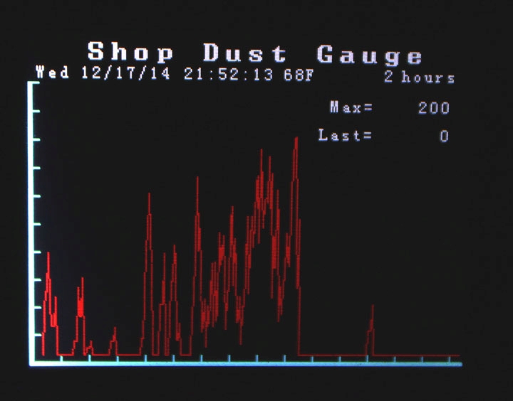
Here is a screen shot:


Above is a screen shot of the gauge's display. (The actual screensize is 3.2 inches on the diagonal.) What you are seeing is a period of inactivity in my shop (the area on the right of the graph) and then the first steep spike you see is when I turned on my random orbital sander. I wasn't actually sanding anything, this was just dust that kicked up from simply turning it on. I admit I hadn't cleaned its cloth bag filter in some time, as there was a slightly detectable cloud of dust that emerged from it when I first turned it on. I was about 6 feet away from the monitor at the time, and after letting it run for about 10 seconds I turned it off and left the room for over an hour. You can see it takes quite some time for the dust to settle down. The two left most peaks represent the two times when I came back into the room to do the photography to take this photo - just moving about in the room stirs up the air a bit. After that, it flatlined.

Besides graphing the data, the device logs the data to an SD card and you can upload a spreadsheet file to your computer for further graphing, etc. and the data displayed on the screen can be filtered and smoothed.

So, if any of you are interested in a device like this, and are willing to build one very soon and tell me about how to make that experience better, please PM me with your email address.  I will not share that address with anyone else.

Thanks,

Revwarguy
#3
Jeez, retired2.  What ever made you think I look at the sep while sawing?  I use a camera.
#4
Thanks, retired2.  I have read it before as well, but I do not understand why "Inlet spin in the same direction of the fan wheel will reduce air volume and pressure ratings." 

I can believe that the air pressure between the straightener and the impeller is lower without the straightener is lower than with it, but it seems like the pressure difference between the other sides of the impeller and the straightener would be the same with or without it.  It seems to me that ultimately the mass/energy calculations here would show energy being expended by the air against the straightener (lost energy) and then more energy being expended by the impeller against the air, all to get the air moving in the same direction again. 

I understand this is all theoretical, but if it has been experimentally determined that a straightener helps even when the direction is the same to any reasonable degree, then I'll add one just to see.
#5
I agree with just about everything retired2 said in his 1st post on this thread.  Until there is a way to actually measure "better separation of fines," most of those enhancements based on it are just unknown, and a slight improvement at best.

I would beg to differ, with utmost respect to retired2, about the transparent sides, though - I think it is an advantage to be able to see if anything is clogging inside, and, well, I just love looking at the swirl.  Maybe that's not worth the expense to some (it didn't cost me anything as I had the stuff already) but I would have paid for the plastic sheet anyway.  Just don't use plexiglass (acrylic) as it will be an exercise in frustration.  My Lowe's carries Lexan and you can find it at sign makers or online.  You don't have to get one long, narrow piece - the walls can be done in sections.  Since you are going to seal the walls in place, you don't need to screw into it, either - it just has to be cut with a tight enough fit to stay in place until the caulk sets up.

Having a transparent wall on the inside of the separator has shown me that with about 1 year's use, there is NO wear, scratching, or dulling of the window from the dust against the material, and I believe that worrying about the walls wearing down is unnecessary.  I have only been collecting sawdust however, not cleaning up after sandblasting equipment.  In that case, you should probably worry more about your hose.

Retired2 is right, though - just doing a basic one will get you very close and one you will be happy with every time you look in your bin.
#6
Very interesting paper, thanks for posting it.

One question I have concerns having a top hat before the DC.  If the direction of the swirl or vortex coming out of the top hat is the same as the direction of the impeller in the DC, isn't that a good thing?

There is no question (at least, in my mind  ;) ) that if the direction of the impeller is opposite of that of the vortex coming from the top hat, then energy must be wasted reversing this flow.  However, if the vortex is straightened out, instead of matching the impeller, doesn't more energy have to be expended by the impeller to move it through the DC?

It seems to me that if you match the direction of the air swirl from the top hat to the DC, a straightener in between would only cause more energy to be wasted.
#7
Hi Jack,
No rabbet was needed in the separator bottom, as the Lexan was just the right length between the rear upright and the end of the C slot at the other end of the curve to hold it in place during assembly.  (The Lexan actually drops down below the bottom of the separator just a bit.) Once assembled, all of the sealing was done on the outside - if you look at the rectangular openings of the Lexan (the area bounded by the top, bottom, and uprights as windows, you caulk them just like any other window, going completely around each opening from the outside.  This not only held the plastic in place, but made a good seal all around.

I used 1/16 in Lexan (a polycarbonate) not Plexiglass (an acrylic) so no heating was needed to bend it.  I do not recommend Plexiglass at all as it is stiff, brittle, and is hard to machine - it melts and cracks way too easily.  Lexan is a little bit more expensive but is a much stronger, tougher, and easier material to work with.  You can bend a piece of Lexan sheet in a vice with a hammer 90 degrees and make an angle bracket!
#8
A set of plans is a bit problematic - you start with the main pieces you want to use, the driving numbers seem to be the size of the pipes (both from the DC and the duct out to the tools - in my case, 4 inches) and the size of the bin or can you will be using.

Then, you do what you can to make something like a pocket slot that will allow a tight fit of the can rim into the bottom of the separator.  From the diameter of this ring, you can set the diameter of the outer ring of the C slot, and that then determines the diameter of the inner slot.  The size of the inlet duct sets the minimum size of the risers (some argue it should be greater than this) between the top and bottom of the separator.  Once you know the diameter of the C slot, you know how long a piece of plastic wall to get.  The diameter of the separator top is just whatever covers the risers, but it is not critical.

If you would like me to take a measurement off of mine, just ask for what you want.
#9
Leaks around the baffle where it touches the can are not too critical, Nerd.

If you need to use a metal garbage can, you might consider a top hat design so that you can get a good seal around the top rim.  I did just that, as shown at http://www.jpthien.com/smf/index.php?topic=952.0

Hope that is some help.
#10
A little more food for thought:

From what you've described, the forces for holding material on a vacuum table while being milled are very different than for dust collection - I would start with 2 separate systems.  I am not sure about those Ridgid vacuums - are they meant for continuous duty?  Many of the smaller vacs are not, and you will probably want to do some 4-8 hour runs if you do any 2.5D (bas relief) type routing.

I have a basement CNC.  Here's my take - think hard about the difference in cost between an enclosure and a spindle.  Most of the noise of a router is its cooling fan.  I was shocked at how quiet the machine was the first time I saw a water-cooled spindle-based CNC table, both while jogging and cutting wood.  For the same reasons, those smaller shop vacs are almost as noisy as a router, but I don't know about that particular Ridgid model.

A well designed shoe should get at least 90% of the dust.  Do one of those first, and see what else you need to do from there, as it then really depends on what you are cutting.

I can sympathize about the noise, for sure.
#11
I've made a video of the dust action of this separator.  It is at the bottom of the webpage here:

http://www.liming.org/dustcollection/.

It shows different material being cut.
#12
Quote from: tvman44 on August 23, 2013, 01:44:11 PM
What did you use for the baffle itself?
Been thinking about redoing one of my separators from the top entry type with the baffle in the barrel and making a top hat for it. :)
As shown on the website, I used 3/4 in mdf.  This is a bit thick for the baffle edge, and that is why I beveled it.  In this approach, the bottom of the separator not only serves as the baffle, but is also the rim seal for the bin, the attach point for the bottom of the Lexan sides, and the attach point for the inlet walls.  Kind of a lot to ask of thin material.  Perhaps a thin top layer for the edge over something that can form a pocket for the bin rim?
#13
Thanks for documenting your build, Kevin.
#14

Hey juice,

Just a thought - how good do you feel about the seal you have all around, including where it sits on the lid?  First time I tried mine, I didn't like the fine sep either, but I was anxious to see it work and hadn't applied the seal yet. Adding the sealing material really helped make the problem go away in my case.
#15
Quote from: codykniffen on August 01, 2013, 09:33:19 PM
Pretty sure I'm going to finally build my top hat based on your design. Wish me luck!

Any questions, fire away.  If I had it to do over, I think I would have used plywood instead of MDF as I had the MDF on hand, but either will work.  I keep using the separator, though, and it seems to work really well.

BTW, calling it my design is stretching it a quite a bit, but I know what you meant.  These collaboration projects can get tricky -  thanks to Phil Thien for the baffle idea, Bruce Wrenn for the Top Hat idea, Rawdawgs50 (aka Pitbull or perhaps Jason ???) for the shell idea, who says he got it from somebody named vawoodworker84, and retired2 for the bell mouth idea. My contribution is that I painted mine red!   :)

When you get it done, or even before, upload some pictures here, OK?