|
 My
drill
press column-mounted fence My
drill
press column-mounted fence
Copyright (c) 2012, all
rights reserved.
My normal drill press table
and fence have served me well, but there was one type of operation
where it fell short: Drilling holes in the EDGES of
workpieces. Especially when the workpieces were larger
rectangles and I needed to drill holes in all four edges. This
would require moving the table, which meant the fence lost registration.
This need arose again when
I was working on a dust shoe for a CNC router (more on that some day
in the future). I had very nicely machined a piece of
polycarbonate (on the CNC router itself) and was now needing to drill
1/8" diameter holes around the perimeter of this 4" x
7" (or so) piece of plastic.
Using the shorter fence on
my drill press table was futile. The fence itself is only about
2" high, so it simply didn't provide enough support near the top
of the workpiece. The result was holes that weren't perfectly
centered in the edges of my little piece of plastic.
Now, if you know anything
about me, you know that just wouldn't do. Because I'm
certifiably insane, I see a line of holes that aren't in perfectly
alignment as abject failure. So it was time for me to revisit
my need for a tall fence, and something that didn't register off the table.
I knew I wanted something
that registered off the column, that would solve both problems I was
having. With a fence registered off the column, the table could
be moved up/down/sideways and neither the fence nor the stop block ON
the fence would move. Also the fence could be placed
immediately below the bit, so my workpiece would be perfectly
supported and my holes would all be in a perfect line.
So I started googling
things like "drill press column fence" and was getting
nowhere. I knew I had seen one design, an old Skil
"HD" (stood for "Heavy Duty" and the stuff was
actually pretty good) had a fence that was an adjustable bar on a
collar that attached to the column. Primitive but...
Nothing else much turned
up. So I decided that once again, I'd need to come up with
something on my own. The pics here are what I've philgineered.
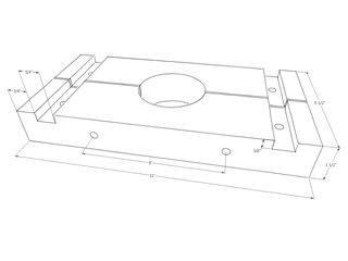
Basically, a nearly
1-1/2" thick piece of Baltic birch plywood (technically two
pieces that are glued-up) is made into an 11" wide split
collar. There are two 5/16-18 carriage screws and knobs that
squeeze the collar around the column. Finally, there are two
dadoes, each 3/4" wide by 3/8" deep in which some Rockler
t-track slides. T-bolts (4) in those dadoes with accompanying
knobs on the bottom snug the t-track up.
The other ends of the
t-track are connected to a small block of wood that is really the
subfence. This block of wood also has some 3/4" wide by
3/8" deep dadoes to capture the ends of the t-track. And
the block has some perpendicular holes (two of them) through which
t-bolts extend. With knobs, these t-bolts snug the actual fence
against which my workpiece rests.
That is a lot of words to
describe what a few pictures will probably do better, so there are
plenty of pictures and an incomplete (I'm working on it, my SketchUp
skills are very slowly improving).
How to make your own...
I always look at pictures
and plans and wonder where exactly to start. Well, I'm going to
give you the exact steps I used to make this one, as best as I can recall.
|
• |
|
Glue up two pieces of
3/4" Baltic birch plywood large enough to net a single piece
11" x 5-1/2" x about 1-1/2" thick. I used the BB
plywood sold as 3/4" thick. It isn't, quite, but whatever
you net from two layers 3/4"-ish thick will be fine. |
|
• |
|
Cut the glued-up piece to
final dimensions (11" long, 5-1/2" wide). |
|
• |
|
You're going to need the
subfence to match the 11" width, so now would be a good time to
also cut a piece of BB plywood that is 11" long by 1-1/2"
wide. Try to use a single stop-block setting while cutting both
the larger block and this sub-fence to the 11" long dimension,
it will save some time in the next steps if they are exactly the same length. |
|
• |
|
Mark the center of the
larger block that will become the collar. You could use a
longer steel rule and draw diagonals, but I typically use a
combination square and make four marks. First, I set the
combination square to half the 11" dimension (so 5-1/2")
and then use it to make a mark from both ends. Now I change the
combination square to half the 5-1/2" dimension and again make
two marks now from both of the long edges. In the middle of
your workpiece you will now have a sort of "#" and you
should be able to visually split the differences very accurately. |
|
• |
|
Measure the diameter of
your drill press column. I used a digital calipers (just a
cheapie I purchased at Harbor Freight, the one that eats batteries
like they grow on trees). I took several readings in a few
different spots along the length of the column, and came up with
2.885". My drill press is a Ridgid floor-standing model, I
imagine column diameters will vary from manufacturer and model to
model, so make sure to measure YOUR drill press column. |
|
• |
|
I now divided my column
diameter in half (1.4425) and adjust my digital calipers to
1.442". I then took a drafting compass and adjusted it
using the calipers. Now draw a circle on your plywood. |
|
• |
|
Now I moved to my router
table to create the dadoes for the t-track. I used a 3/4"
router bit and made a few passes to get to the 3/8" depth I
needed. I used a scrap piece of wood behind my workpiece to
prevent the bit from blowing-out when it exited. |
|
• |
|
Now is the time you also
want to route those dadoes in the sub-fence. If you do it now,
the dadoes between the collar and the subfence will align nicely when
it comes time to assemble the thing with the t-track. |
|
• |
|
Now mark your workpiece for
the carriage screws that will soon squeeze the collar to the
column. In my case these carriage screws are 5" apart, or
2-1/2" in each direction from the centerline. Mark your
lines on the top of your workpiece. |
|
• |
|
Now we get to cut the
collar in half. Align the fence of your table saw so the blade
will as nearly as possible tip the collar into two equal halves. |
|
• |
|
Use a bandsaw or scroll saw
or jigsaw to cut the column hole from the two halves of your
collar. I used my little Skil bench bandsaw with a 1/4"
6-TPI blade. Stay inside the line. |
|
• |
|
To fine-tune the cut, I
alternated between test-fitting the collar halves to the column, and
sanding them on my oscillating belt sander. A drum sander would
also work great for this. Just take your time, sand to the line
slowly, test your fit. I probably test-fit ten times for each
half of the collar, and stopped once the collar halves nicely fit the
column with no gaps. |
|
• |
|
Now drill the holes for
your carriage bolts. I used a saddle square to transfer the
lines I had made on the top of the collar back in step #9 to the
INSIDE of the two collar haves (the sides that will be TOWARDS the
column). And then I found the center of the edge using my
combination square set at half the thickness of the piece, and making
two marks. The difference between the two marks is the
center. I drilled 5/16" holes through each half of the collar. |
|
• |
|
If your drill press has a
rack for raising/lowering the table, you need to accommodate it by
notching the block. I did this on my table saw, nibbling enough
material away from both halves of the collar so the rack wouldn't interfere. |
|
• |
|
Now we can do our first
test tightening. Install the two carriage bolts through the
holes (I seated the heads with a hammer) and assembled the collar
around the column, and used a couple of knobs to snug everything
up. I found I get the best results with one smaller knob and
one larger ratcheting knob. I snug the little knob, and then
crank the ratcheting knob a bit. Once snug try moving the
collar by grabbing it with both hands and twisting it. It
shouldn't budge. |
|
• |
|
Now take it all apart again
and drill your 5/16" holes for the t-bolts. There are four
holes (two in each collar half) and two more in the subfence.
Just center these both length and width-wise in the dadoes. A
good trick for finding marking the center of the dado is to use a
3/8" gauge block and draw two lines and divide those by eye. |
|
• |
|
You will need to drill two
holes into the edge of the subfence for the t-bolts that hold the
actual fence. I can't remember where I placed these, I
will update this page if anyone actually tries building one of these. |
|
• |
|
Make a fence. I make
these from 1" thick wood and I route a t-slot into each
side. The one I'm using now is 1" plywood (actually a
piece of 3/4" and 1/4" scrap glued together). The
t-slot on back allows for mounting the fence to the subfence.
The t-slot on front allows me to add a stop-block. To route a
t-slot, I use a 3/8" straight bit to remove most of the
material, and then a Rockler or Whiteside t-slot bit to finish it
off. A router table is invaluable for this. |
|
• |
|
Now reassemble once
again. You need a couple of 1' long pieces of t-track, some
t-bolts (four to hold the t-track in the dadoes on the collar, two
sets to hold the t-track to the subfence, and two to hold the fence
to the subfence. |
Random notes...
|
• |
|
The t-bolts I used in the
collar didn't extend much below the bottom, I was concerned the knobs
wouldn't get much purchase on them. I ended-up adding a 1"
counterbore (you can use a Forstner bit, I used a piloted
counterbore). I went 1/4" deep.\ |
|
• |
|
The 5/16" holes can be
a little tight for 5/16-18 t-bolts and carriage bolts. My
5/16" drill bit may be a few thousandths undersized, too.
So when I was all done, I reamed-out all my 5/16" holes to
21/64" (this is 1/64" larger than 5/16"). |
|
• |
|
I didn't write-up anything
on making a stop-block, but I'll picture mine here soon.
I use this same stop block for both my drill press and table saw
sled fences. It has a ridge which rides in the t-slot so the
block doesn't twist, and a t-bolt and knob snug it up. |
|
• |
|
You may notice I used some
wingnuts and some knobs on my jig. I didn't do this for any
other reason than I was out of knobs and the prices on those things
is about $1.50 each. A recent PayPal contribution was used for
the t-track, and there wasn't enough left for knobs, so wingnuts it was. |
If you spot any errors or
there is any confusion, please let me know so I can update this
page. I plan on updating it to get rid of the red. This
has been sitting on my hard drive, unpublished, for a couple of
months now. Sometimes the best way for me to get in gear is to
just get in gear, so I'll fix the missing parts soon. Here is a <link>
(soon) to a file with my SketchUp file for the collar.
I haven't drawn the subfence and there is no way my skills are
currently up to adding carriage bolts or t-nuts or t-track,
sorry. I think there is plenty there for the builder, though.
--Phil
phil@cgallery.com
This page has been viewed 12646 times. |