|
Fine-tuning
your Ryobi BT3000/BT3100/BT3K
table saw
When properly aligned, the
BT3K cuts as precisely as the finest cabinet saw. The saw's
manual does a very good job of laying out alignment procedures that
get it "close enough." Considering that the writers
of the manual had to assume the only calibration tool at the disposal
of the reader was a square, I think their work is quite an achievement.
Of course, "close
enough" isn't good enough, and we want our saws to be
perfect. If you've flipped through woodworking catalogs at all,
you've no doubt noticed tools for aligning table saws. These
are typically aluminum bars that ride in the miter slot and which
hold a dial indicator perpendicular to the slot. Here
is a link to a typical design. They allow users of
contractor saws to align the blade to the table with great
precision. But wait, the BT3K saws don't have miter slots.
And you can't adjust the relationship of the blade to the table,
either. The BT3K is unique, and requires a unique approach.
That is what I offer
here. With a 3" x 10" block of 3/4" plywood, a
bolt & cross-dowel, and an inexpensive indicator (digital or
dial), you can align your BT3K to perfection.
|
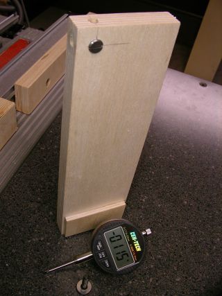 |
This is my BT3K
alignment block.
Made from a 3/4" piece
of BB plywood. I used a cross-dowel and two holes drilled
1/2" from the edge. This allows me to arrange my indicator
in the three different configurations I use. The small piece of
1/4" BB at the bottom acts as a fence when aligning the SMT base.
 No
precision machining is necessary, the only prerequisite is that the
indicator is securely held. No
precision machining is necessary, the only prerequisite is that the
indicator is securely held.
|
|
Procedure
#1, Check the arbor/blade
runout |
|
 |
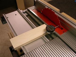
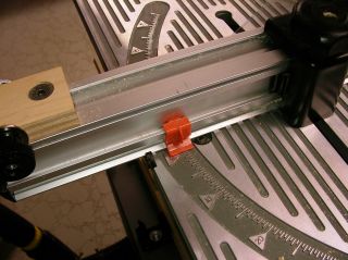
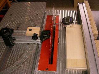
Assemble the alignment jig
in the fashion shown in the photo. The small block of wood
(a.k.a., "the fence") is UP. Set the saw's fence
5-1/2" from the blade and insert the jig. Zero the
indicator. Carefully rotate the blade while observing the
indicator for the range of values.
My
combined (arbor + blade) runout is .004" (four-thousandths of
an inch). Assuming the blade is perfectly flat (they aren't),
that translates into .0005" of arbor runout [that is .004"
/ 8" (the radius point on the blade where you measure times two)].
If
your total measured runout is more than .005", I suggest
removing the blade and cleaning the arbor nut, washers, spacers, and
flange. Clean them with Formula 409. Reassemble and try
again. If you are still measuring significant runout, try a
different blade.
I
experienced excessive runout (I could see the blade wobble while it
was spinning down) and discovered that my spacers weren't flat.
Replacement spacers from Ryobi fixed it right up. |
|
Procedure #2,
Align base of SMT to the blade |
|
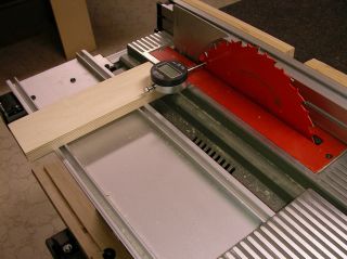 |
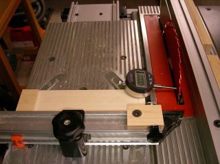
Your SMT base need to be
perfectly parallel to the blade. Follow these steps to check
its alignment: (1) Configure your jig as in the photo to the
left. The jig's "fence" is DOWN. (2) Raise the
blade as high as it will go, then back it off about .1".
(2) Mark a tooth with an "X" and rotate the blade so this
tooth is towards the front of the saw. (3) Push the indicator
point against the "X" until the jig's fence is flat against
the SMT base. (4) Zero the indicator. (5) Rotate the
blade so the tooth you marked with an "X" is at the rear of
the saw. (5) Move the jig to the rear of the blade and push the
indicator point against the "X." Your indicator
should read zero (0), showing no difference in measurement from front
to back. If not, try again a few times until you are
comfortable with the procedure and to make certain you get repeatable results.
|
|
|
Use the instructions in the
manual (bottom of p. 33), "MAKING ADJUSTMENTS TO SLIDING MITER
TABLE ASSEMBLY/TO ADJUST THE MITER BASE" to make any necessary
adjustments. Once you have made the necessary changes repeat
this section to verify your base is parallel to the blade. |
|
|
Procedure #3,
Align
the miter fence to the blade |
|
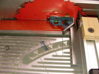 |
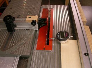
Install the miter fence on
the sliding miter table and set it to 90-degrees (make certain you
use the orange indicator shown in the photo at left). The
graduations are rather thick, so I place the orange indicator to the
top of the graduation. You can use the top, middle, or bottom,
as long as you're consistent.
Now
place your square against the blade and the fence and check your alignment.
|
Use the instructions in the
manual (top of p. 34), "MAKING ADJUSTMENTS TO SLIDING MITER
TABLE ASSEMBLY/TO ADJUST THE MITER FENCE" to make any necessary
adjustments. Once you have made the necessary changes repeat
the steps above to verify your fence is square to the blade. |
|
|
Procedure #4,
Verify alignment
of SMT to blade |
|
 |
In procedure #2 above we
made certain the SMT's base was parallel to the blade. Having
done that, the sliding miter table should automatically slide
parallel to the blade. But we may as was well check.
[Trust, but verify.]
Use
the following steps: (1) Configure your jig as in the photo to
the left. The jig's "fence" is UP. (2) Raise
the blade as high as it will go, then back it off about
.1". (2) Mark a tooth with an "X" and rotate the
blade so this tooth is towards the front of the saw. (3) Push
the indicator point against the "X." (4) Zero the
indicator. (5) Rotate the blade so the tooth you marked with an
"X" is at the rear of the saw. (5) While holding the
jig against the fence, carefully slide the table towards the back of
the blade until your indicator point rests on the "X"
again. Your indicator should read zero (0), showing no
difference in measurement from front to back. If not, go back
to "Procedure #2, Align base of SMT to the blade" and check
your work. |
|
Procedure #5,
Align the rip
fence to the blade |
|
 |
We're almost done! We
just need to align the rip fence to the blade. The fence should
either be perfectly parallel to the blade, or toed-out (away from the
blade at the back) by a couple thousandths of an inch.
Toeing-out the fence is less important if you use a splitter. I
shoot for parallel.
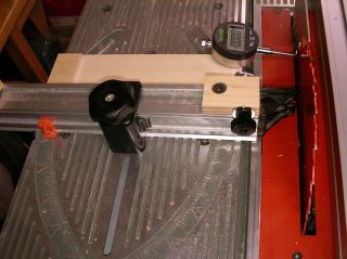
Here
is the procedure: (1) Assemble the jig as shown in the
photo. The jig's fence is UP. (2) Raise the blade as high
as it will go, than back off by about .1". (3) Mark a
tooth with an "X" and rotate the blade so the tooth is
towards the front of the saw. (4) Lock the fence approx.
5-1/2" inches from the blade. This allows the jig to slide
between the blade and the fence, so the indicator point is always in
contact with the blade and the right edge of the jig is always in
contact with the fence. (5) With the edge of the jig against
the fence and the indicator point against the "X," zero the
indicator. (6) Rotate the blade so the marked tooth is towards
the rear of the saw. (6) Slide the jig to the rear of the blade
and place the indicator tip on the "X." Take a
reading on the indicator. It should be zero (0).
|
To make adjustments, follow
the instructions on top of p. 29 of the manual ("TO CHECK THE
ALIGNMENT OF THE RIP FENCE TO THE BLADE"). Once you've
made any changes, repeat the steps in this section to verify the
fence is now properly aligned. |
|
|
Procedure #6
(Optional),
Check the blade for 90-degrees |
|

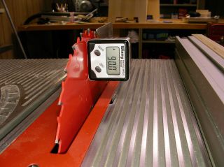 |
Extra Credit:
The five procedures above don't really require that the blade be set
to 90-degrees to work correctly. However, most of my cutting is
done at 90, so I like to make certain I have my blade set
correctly. I use my Wixey Digital Angle Gauge to do this.
Set the gauge on the table and zero it. Then attach it to the
blade and adjust the blade until you read 90-degrees. Spot-on! |
Some final thoughts...
(1) Depending on where you
keep your SMT on the rails, you may need to adjust the size/shape of
your jig. My SMT is to the immediate left of my table, so that
is how I arrived at the size/layout of my block.
(2) I have found that
raising the blade all the way to the top (where you begin to feel
resistance) causes up to .006" of distortion from the front to
the back of the blade. All you have to do to correct this is
lower the blade about .1"
(3) It is necessary for the
SMT table to slide on its base with no side to side play. See
p. 33 of the manual to eliminate play in the table. If you have
any difficulty moving the table after this, wax the edges of the SMT
base (use some wax paper, or some Johnson's paste wax, or my
favorite, Waxilit). If it is still difficult to move, you
tightened it too much. :-)
(4) When taking readings
using the jig, it is possible to distort the readings by pushing down
or sideways on the jig with any force. Apply the minimum
pressure necessary to get an reliable reading.
--Phil
phil@cgallery.com
This page has been viewed 47390 times. |